1.Features:
1. Ultra-low vibration and noise
2. Maximum peak current: 5A
3. Impulse response frequency: 200KHz
4. Subdivision: 200~51200ppr
5. Voltage: 24~80VDC
6. Variable current control, motor heating is greatly reduced
7. Protection functions such as overvoltage, overcurrent, tracking error out of tolerance, etc.
8. Closed-loop vector control to ensure high-speed and high-torque output of the motor, and ensure that the motor does not lose steps
9. Signal input: pulse + direction or double pulse (differential), compatible with 5~24V signals without series resistance
10. Serial communication function, current, subdivision can be adjusted arbitrarily, signal edge, alarm output logic and other functions are adjustable
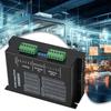
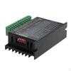
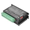
2.Overview:
HBS57H uses the latest dedicated motor control DSP chip and vector closed-loop control technology to completely overcome the problem of open-loop stepper motors losing steps, while significantly improving motor high-speed performance, reducing motor heating and reducing motor vibration, improving machine processing speed and accuracy, and reducing Machine energy consumption. When the motor is continuously overloaded, the driver will output an alarm signal in time, which has the same reliability as the AC servo system. HBS57H is adapted to 57 series closed-loop stepper motors, which facilitates the upgrade of traditional stepping system solutions, and the cost is only 50% of the AC servo system.
3.Note: The cable connecting HBS57H to the PC, text display or STU servo debugger must be a dedicated cable (purchase required). Please confirm before use to avoid damage.
4.Status indication
The green LED is the power indicator. When the drive is powered on, the LED is always on; when the drive is powered off, the LED is off. The red LED is a fault indicator. When a fault occurs, the indicator flashes in a cycle of 5 seconds; when the fault is cleared by the user, the red LED is always off. The flashing frequency of the red LED is 2Hz, where the LED is on for 200ms and off for 300ms.When the drive fails, the drive will stop and prompt the corresponding fault code. The fault can be cleared only when the user needs to power off and power on again. When the drive fails, the drive will store the latest faults in the drive's EEPROM in a queue format, and the drive can store up to 10 latest historical faults. The user can read the corresponding fault code through the PC and text display.
5.Control signal port
Name description
PUL+/PUL-: Pulse input signal: The effective edge of the pulse is adjustable, and the default pulse rising edge is effective; in order to respond reliably to the pulse signal, the pulse width should be greater than 1.2μs. 5~24VDC level compatible. In double pulse mode: CW
DIR+/DIR-: Direction input signal: high/low level signal. To ensure reliable commutation of the motor, the direction signal should be established at least 5μs before the pulse signal. 5~24VDC level compatible. In double pulse mode: CCW
ENA+/ENA-: Enable control signal, this input signal is used to enable or disable driver output. When ENA is connected to low level (or the internal optocoupler is turned on), the drive will cut off the current of each phase of the motor so that the motor is in a free state and does not respond to input signal pulses. When this function is not needed, the enable signal terminal can be left floating. 5~24VDC level compatible.
Pend+/Pend-: signal output in place, open-collector form, pull-up resistor must be used when using 5V\12V\24V separately
0.5K\1K\2K resistance (this signal can be extended and used, after the driver cover is opened, there is a reserved socket)
ALM+/ALM-: fault signal output, in the form of open collector, must use pull-up resistor 5V\12V\24V to use separately
0.5K\1K\2K resistance, fault output logic can be set by PC software
Brand Name:None
Motor Type:Stepper Motor
Certification:CE
Origin:CN(Origin)
Power Supply:DC
Model Number:HBS57