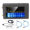
Feature:
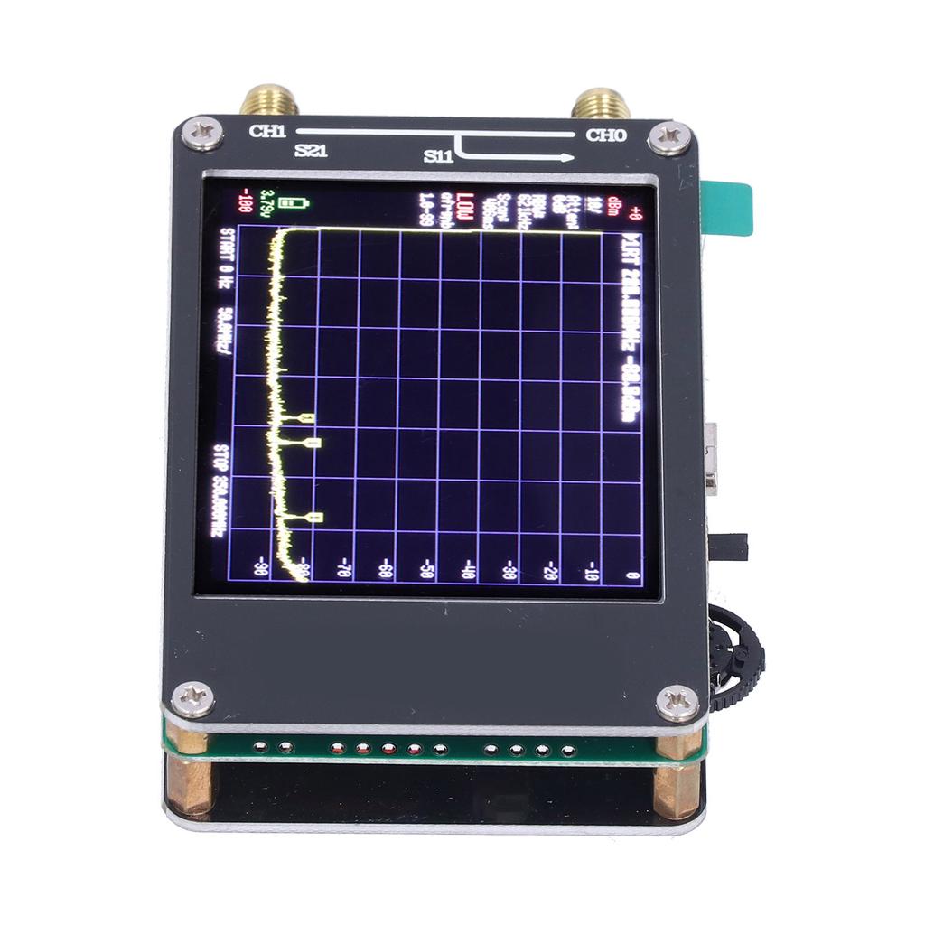
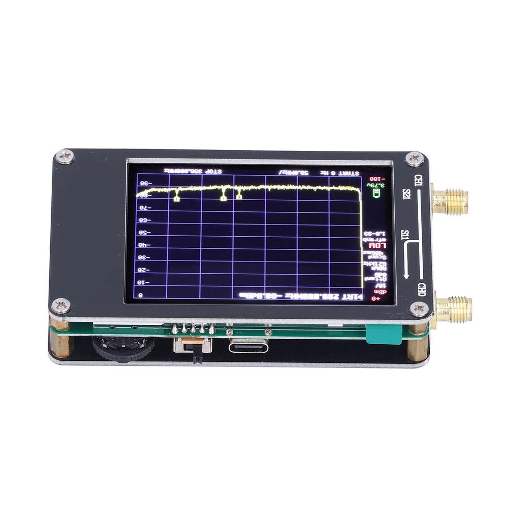
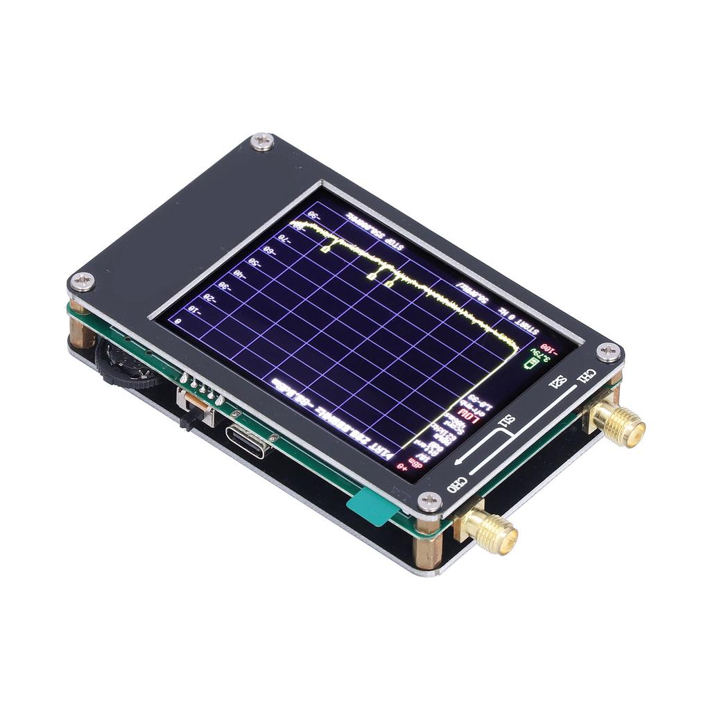
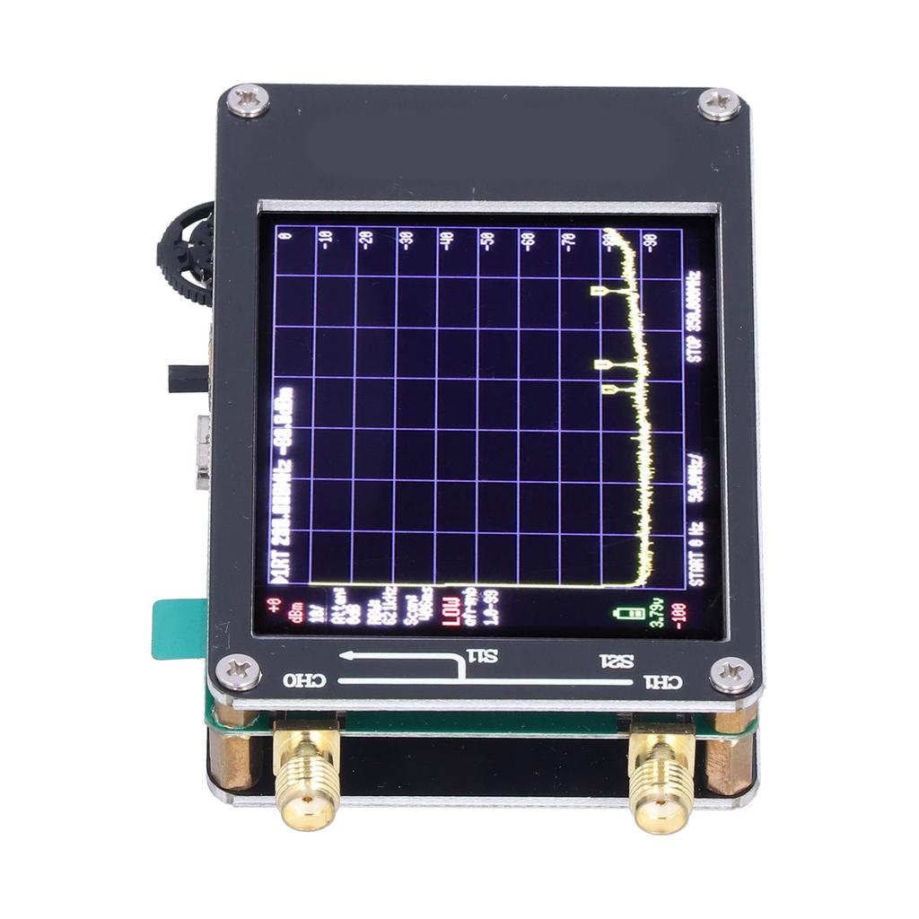
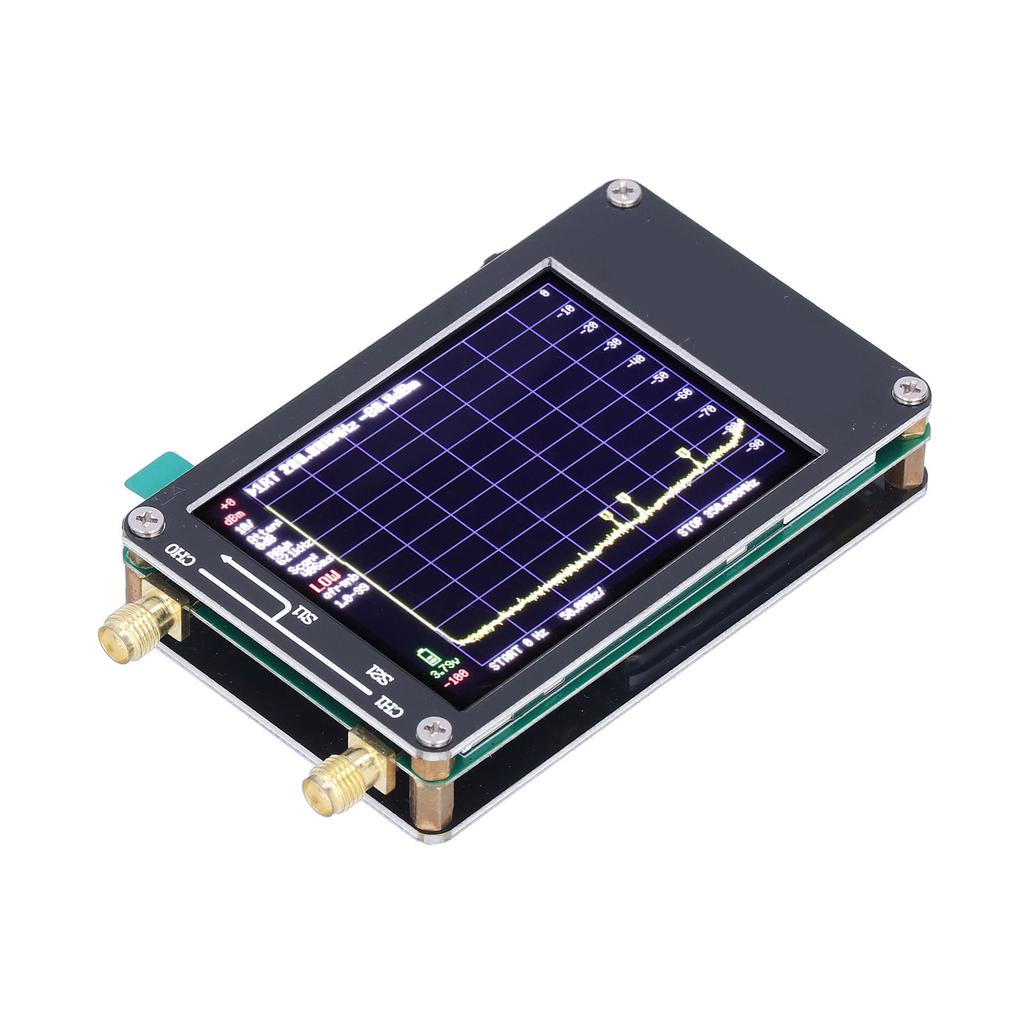
1. The spectrum analyzer has two inputs, high quality MF HF VHF input 0.1MHz?350MHz, high quality UHF input 240MHz?960MHz.
2. The built in calibration signal generator is used for automatic self check and low input calibration. When not used as a spectrum analyzer, which can be used as a signal generator. MF HF VHF sinus output is 0.1MHz?350MHz, UHF square wave output is between 240MHz?960MHz.
3. The spectrum analyzer can switch the resolution band pass filter between 2.6khz and 640khz. The Colour display shows 290 scan points, covering the entire low or high frequency range.
4. The spectrum analyzer can be connected to a PC via USB to become a PC controlled spectrum analyzer.
5. This is a spectrum analyzer for rechargeable batteries, allowing at least 2 hours of portable use.
Specification:
Item Type: Spectrum Analyzer
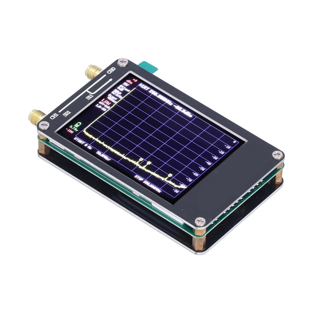
ABS Shell: Approx. 58.7mm x 91.3mm x 17.1mm 2.3 x 4 x 1in (Excluding Protrusions)
Frequency Accuracy: <2ppm
Frequency Stability: <1ppm
Display: 2.8in TFT (320 x 240) Resistive Touch Screen
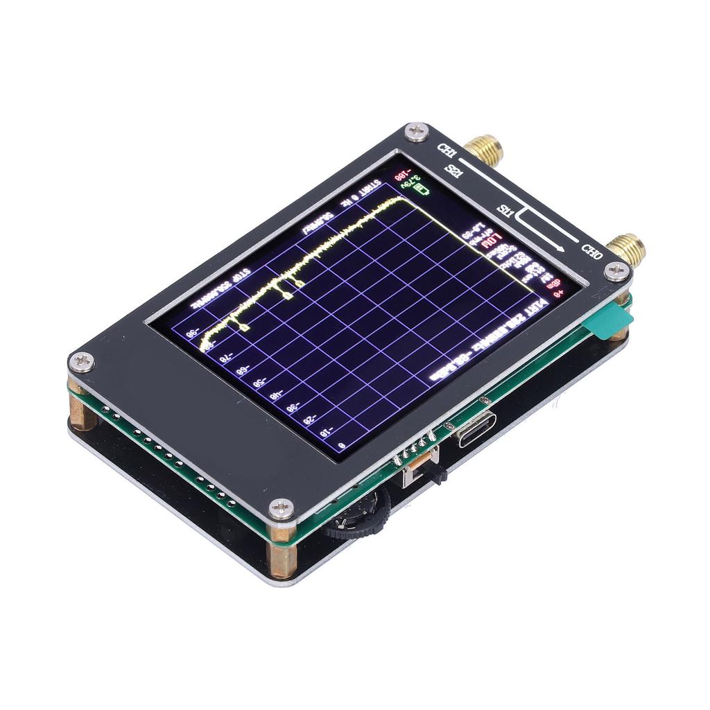
USB Interface: USB Type C Communication Mode: CDC (Serial)
Power Supply: USB 5V 150mA, Built in 650mAh Battery, Maximum Charging Current 300mA, Use Time 2 Hours (Built in Battery Shipped)
How to Use:
Low Input Mode Specifications:
Input Frequency Range: 100kHz350MHz
Pre attenuator: 0dB31dB, step 1dB manual and automatic input attenuation
Absolute Maximum Input Level: +10dBm without attenuation
Damage Level: +20dBm
Third order Modulation (IIP3) Input Intercept Point: +15dBm at 0dB attenuation
1dB Compression Point: +2dBm at 0dB attenuation
Power Detector Resolution: 0.5dB+1dB.
The Lowest Recognizable Signal: 102dBm at 30kHz RBW.
The phase noise at 100kHz offset is 90dBHz, and the phase noise at 1MHz offset is 115dBHz.
When using a 30kHz resolution bandwidth of 70dB, there is no spur dynamic range.
The resolution filters of 3, 10, 30, 100, 300, 600kHz can be manually selected. One of 57 resolution filters is automatically selected.
The resolution on the screen is 51, 101, 145 or 290 measurement points.
Using the maximum resolution filter, the scanning speed exceeds 1000 points sec.
Automatically optimize the actual scan points to ensure that the entire scan range is covered, no matter what resolution bandwidth is selected.
Spur line suppression option is used to evaluate whether certain signals are generated internally or actually exist in the input signal.
High Input Mode Specifications: (High input mode is a low IF reception realized by the second receiver, without pre image and spurious filters)
Input Frequency Range: 240MHz to 960MHz
The input impedance is related to the frequency and deviates from 50 ohms.
Since there is no input band filter, strong input signals outside the range of 240MHz to 960MHz will cause in band signal distortion.
Absolute maximum input level without attenuation +10dBm.
The third order modulation product (IIP3) with an input intercept point of 5dBm.
The 1dB compression point is at 6dBm with no attenuation.
The resolution of the power detector is 0.5dB, and the frequency linearity is +1dB.
The absolute power level accuracy after power level calibration is + 1dB.
Use the lowest discernible signal with a resolution bandwidth of 115dBm of 30kHz.
Frequency accuracy is equal to the selected resolution bandwidth
When using a 30kHz resolution bandwidth of 50dB, there is no spur dynamic range.
The resolution filters of 3, 10, 30, 100, 300, 600kHz can be manually selected. One of 57 resolution filters is automatically selected.
Optional 25dB to 40dB frequency dependent input attenuator. After activating the attenuator, the power level error increases to +10dB.
The screen resolution is 51, 101, 145 or 290 measurement points.
Using the maximum resolution filter, the scanning speed exceeds 1000 points sec.
Automatically optimize the actual scan points to ensure that the entire scan range is covered, no matter what resolution bandwidth is selected.
Low Output Mode Specifications:
Sine wave output, harmonics are lower than 40dB of the fundamental wave.
The output frequency range is from 100kHz to 350MHz (the minimum frequency step is 312.5Hz)
The output level can be stepped by 1dB between 76dBm and 6dBm
Optional AM, narrowband FM and broadband modulation or sweep output on selectable frequency span
(AM modulation function is realized by quickly changing the pre attenuator, and FM modulation is realized by quickly changing the output frequency. It is not a standard and accurate modulation. It can be used for simple walkie talkie reception tests, but it cannot be used as an accurate reference)
High Output Mode Specifications
Square wave output
Output frequency range from 240MHz to 960MHz (minimum frequency step 312.5Hz)
The output level can be selected in variable increments between 38dBm and +13dBm (higher attenuation is achieved using radio frequency switch leakage, and the attenuation becomes larger as the frequency increases, and there will be a relatively large error)
Narrowband FM and broadband modulation can be selected, or slow frequency sweep in the selectable frequency range (FM modulation is achieved by quickly modifying the output frequency, not standard and accurate modulation. It can be used for simple walkie talkie reception testing, but it cannot be used as an accurate reference. )
Reference signal generator specifications (used for self check or output reference clock for external equipment)
Optional square wave output, the basic value is 25dBm, connected to high input output.
The frequency can be set to 1MHz, 2MHz, 4MHz, 10MHz, 15MHz or 30MHz.
Limitation
Since the selection of tinySA internal components has achieved a careful balance between performance and cost, you must be aware that tinySA has great limitations compared to professional spectrum analyzers.
Internal phase noise sets a clear lower limit for phase noise measurement.
The minimum resolution bandwidth of 3kHz makes it impossible to see more spectral details.
The image rejection of high input (240MHz to 960MHz) is very limited, and there is only one level of optional built in attenuator, which makes it difficult to distinguish complex signals..
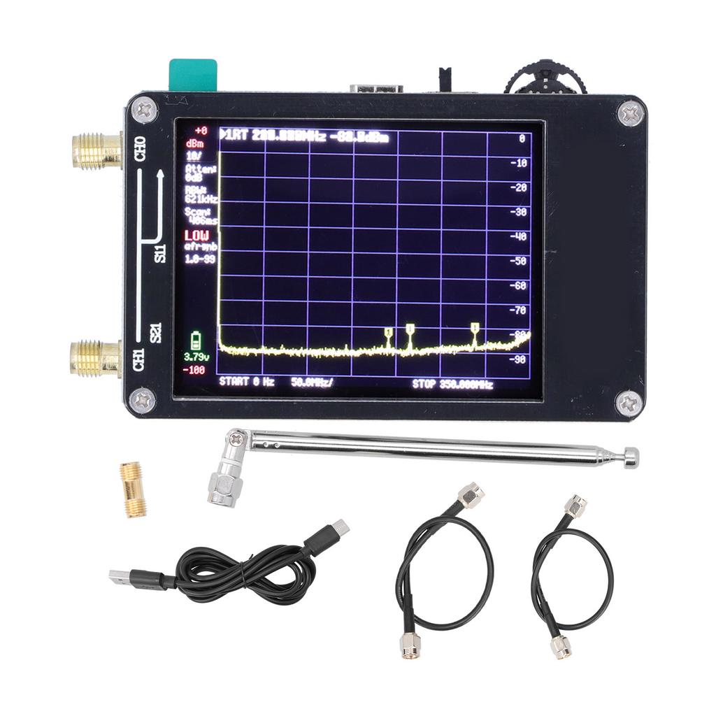
Package List:
1 x Spectrum Analyzer2 x RF Cable1 x USB Cable1 x Connector1 x AntennaThe spectrum analyzer has two inputs, high quality MF HF VHF input 0.1MHz?350MHz, high quality UHF input 240MHz?960MHz.
The built in calibration signal generator is used for automatic self check and low input calibration. When not used as a spectrum analyzer, which can be used as a signal generator. MF HF VHF sinus output is 0.1MHz?350MHz, UHF square wave output is betwee
The spectrum analyzer can switch the resolution band pass filter between 2.6khz and 640khz. The Colour display shows 290 scan points, covering the entire low or high frequency range.
The spectrum analyzer can be connected to a PC via USB to become a PC controlled spectrum analyzer.
This is a spectrum analyzer for rechargeable batteries, allowing at least 2 hours of portable use.